Scan-to-CAD Services
Scan-to-CAD Services
Schimmel Engineering converts physical parts into CNC-ready parametric CAD models — physical part, to point cloud, to fully editable SolidWorks geometry. Capture is done with precision laser scanning at 0.025mm accuracy and NIST-traceable. We extract design intent from the scan data, not just a mesh — led by a Tennessee-licensed Professional Engineer, serving clients in Nashville and nationwide.
Physical Part → Point Cloud → Parametric CAD Model
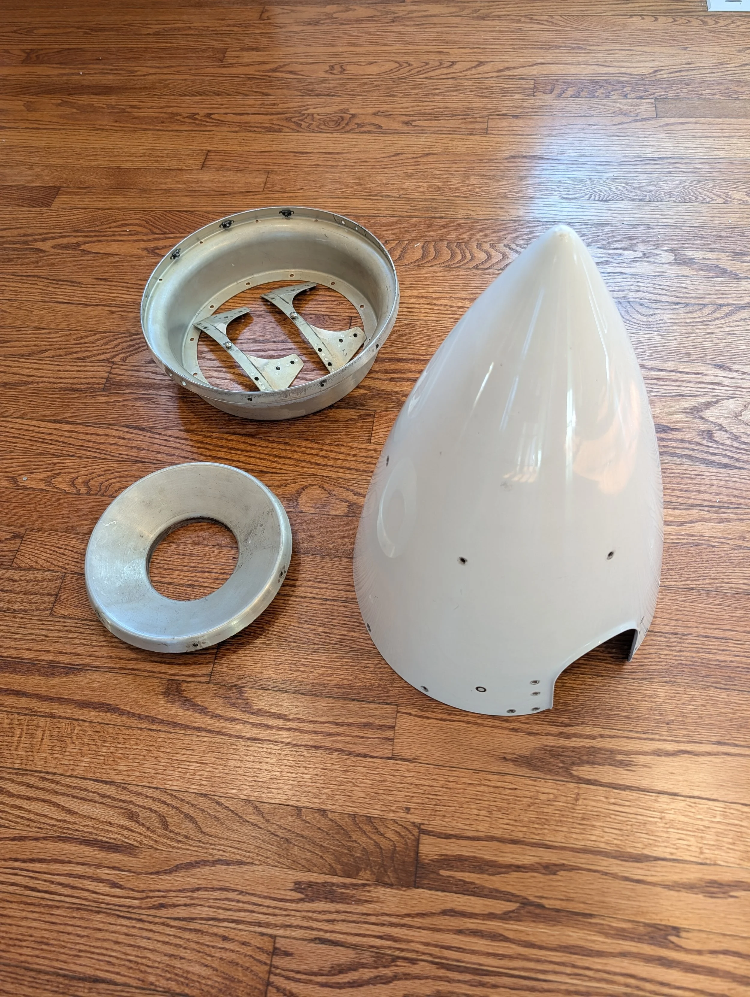
Scan-to-CAD conversion is the process of turning a real, physical part into an editable digital model your team can actually design with. Schimmel Engineering captures the part with a Creaform HandyScan at 0.025mm accuracy, processes the resulting point cloud in Creaform OS 2.2, and rebuilds the geometry as a fully parametric SolidWorks model — dimensioned, feature-based, and ready for CNC machining.
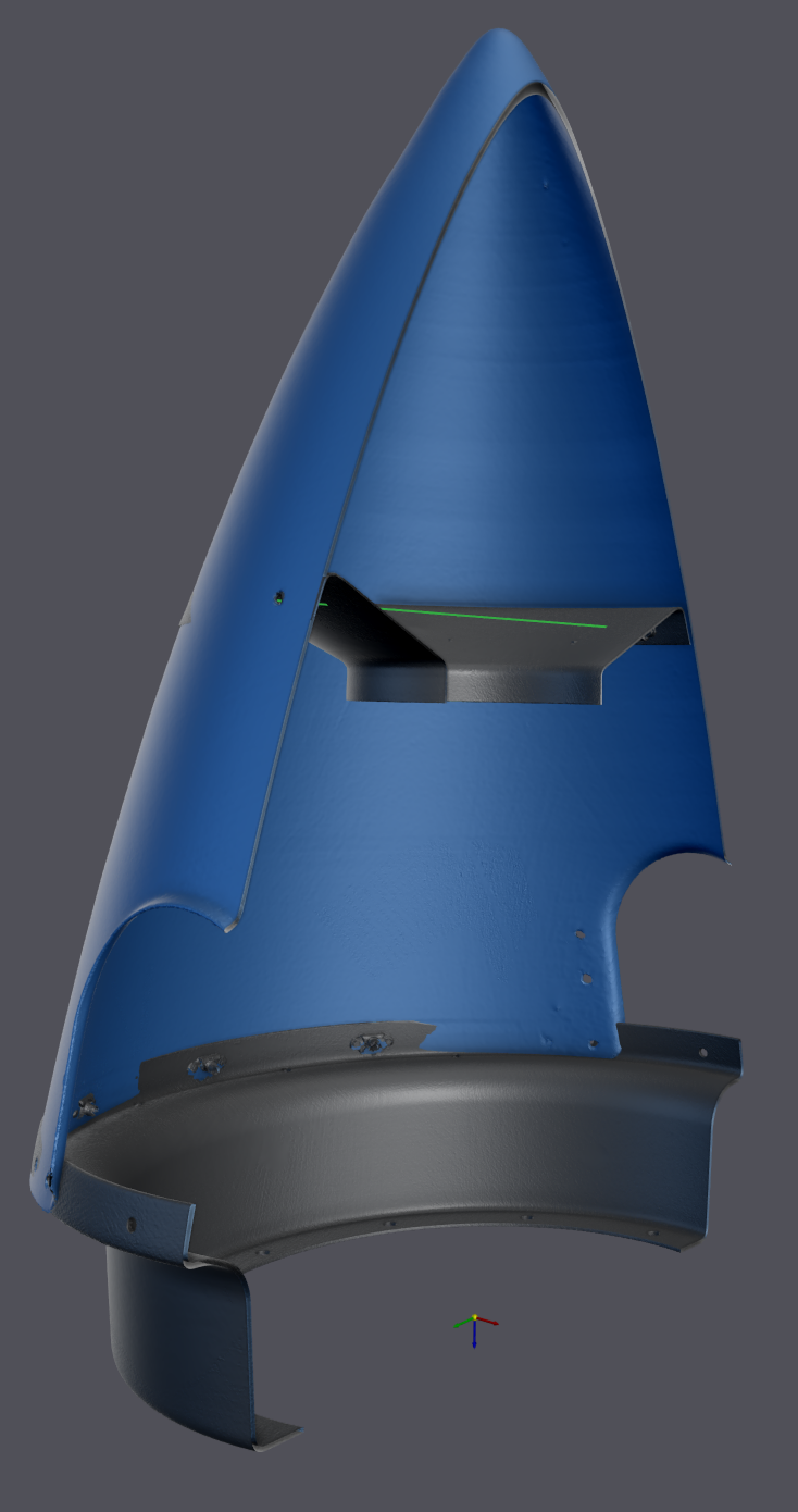
A mesh file (STL/OBJ) is a digital photograph of a surface. It's useful for reference or printing, but most shops can't machine from it and no engineer can edit it. Our scan-to-CAD deliverable goes further: we extract the original design intent from the scan data — bore centers, parting lines, wall thickness, draft angles — and rebuild it as a solid model with proper GD&T, not a static shape.
This is the same underlying process behind our reverse engineering work, but scan-to-CAD conversion on its own doesn't assume you're reproducing a discontinued part. It's just as often used to establish a CAD baseline for a part still in service — tooling, a fixture, or an assembly with no drawings on file.
What Does a Scan and a Parametric CAD Model Look Like?
Rotate, zoom, and inspect both side by side — this is the level of detail we capture, and what it becomes once it's rebuilt as an editable model. Want to inspect the real files yourself? Download a free sample mesh and STEP solid to see exactly what a scan-to-CAD deliverable looks like.
Precision Scan Data — 1979 Austin Mini
Scanned by Schimmel Engineering. This is the raw scan data before any CAD reconstruction begins.
Reverse Engineered CAD Model — Billet ZA70 Engine Case
The same workflow taken to a fully parametric SolidWorks model — every bore, parting line, and mating surface defined and editable. This exact model went into a real production run of 25 units.
The Scan-to-CAD Pipeline
Every conversion follows the same structured path from physical part to finished model.
See the Full 6-Step Process
 STEP 1
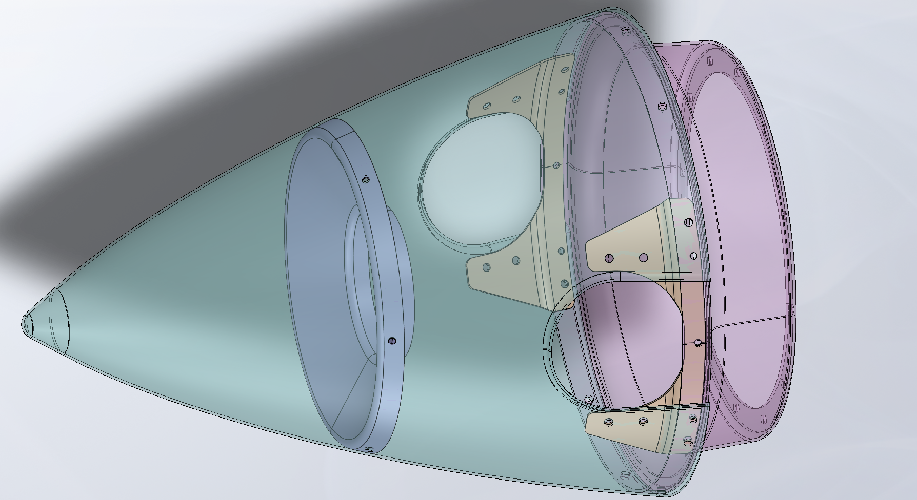
Point Cloud Capture
The part is laser scanned with a Creaform HandyScan at 0.025mm accuracy, NIST-traceable, producing a high-density point cloud of every surface, bore, and feature. No damage or surface prep required. Mail-in or on-site.
.png?content-type=image%2Fpng) STEP 2
STEP 2Point Cloud Processing
Scan data is aligned, cleaned, and merged in Creaform OS 2.2, producing a watertight, accurate reference mesh that becomes the foundation for modeling.
 STEP 3
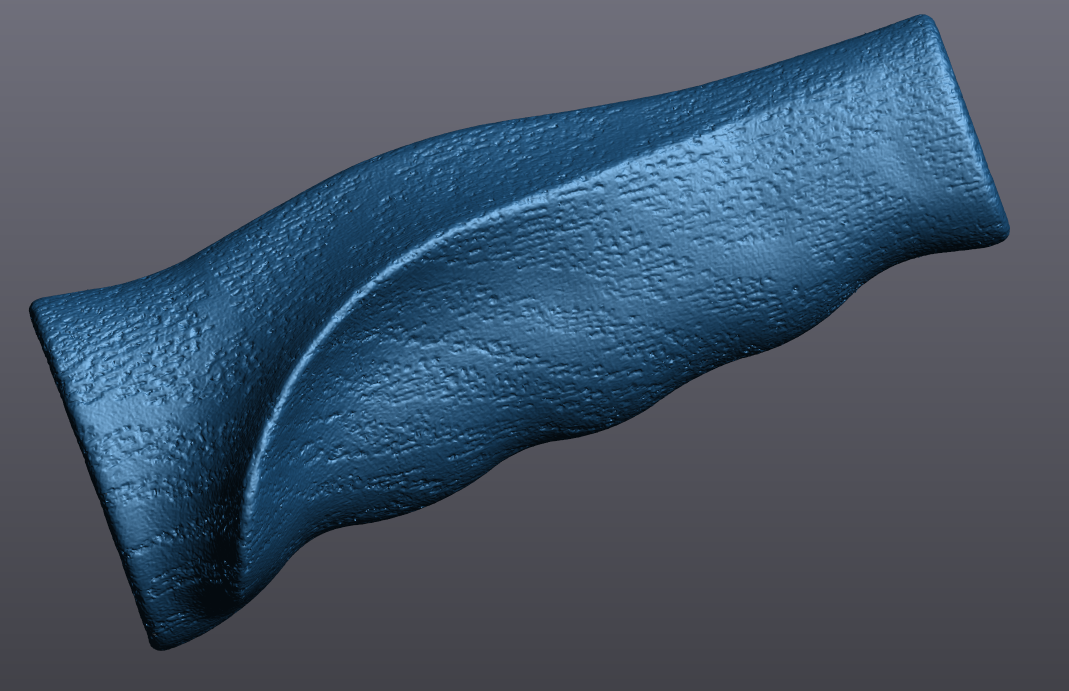
Design Intent Extraction
Critical geometry — bore centers, parting lines, symmetry, mating surfaces — is identified from the scan data. This is where a scan turns into an engineering model instead of a copied shape.
Parametric CAD Modeling
The part is rebuilt feature-by-feature in SolidWorks as a fully parametric, editable model — not a mesh or dumb solid — ready for redesign, assembly fit checks, or direct CNC programming.
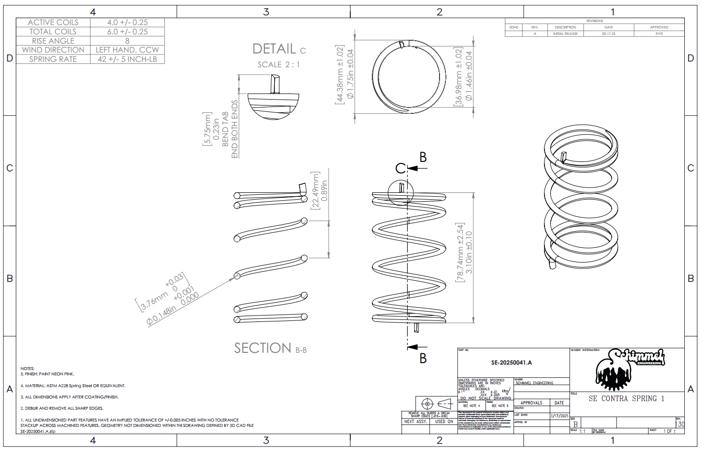
GD&T Manufacturing Drawings
Complete 2D drawing packages with GD&T callouts, tolerances, and material specs, formatted for a machinist or manufacturing vendor.
 STEP 6
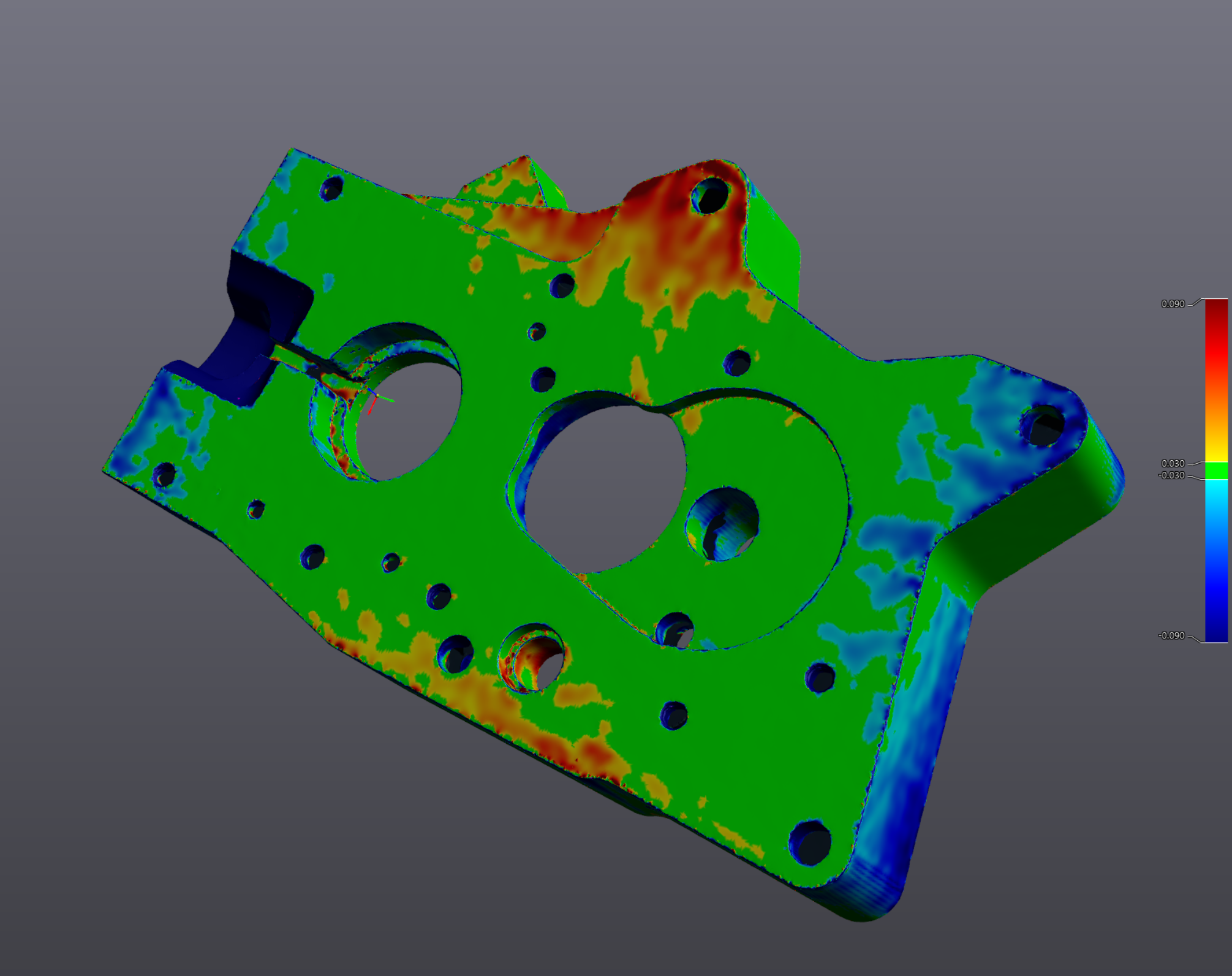
Dimensional Verification
The finished CAD model is checked back against the original scan data before delivery, confirming the model matches the part within scan tolerance.
What You Actually Get
The deliverable is a CNC-ready parametric SolidWorks model — native part and assembly files plus STEP for cross-platform compatibility — not a mesh, and not a "close enough" solid built from calipers and guesswork. See it firsthand: download a free sample mesh and STEP file before you commit to a project.
Native CAD Files
SolidWorks part and assembly files, fully parametric and editable, plus STEP output for use in any major CAD system.
Manufacturing Drawings
2D drawings with GD&T, tolerances, and material callouts, formatted for a CNC machinist or manufacturing vendor.
Reference Point Cloud & Mesh
Raw scan data and a cleaned STL/OBJ mesh available on request for archival records or 3D printing reference.
Trusted By
.png)



What Clients Say About Our Scan-to-CAD Work
Your scans were very helpful. The center line helix was key. I had no problem downloading the files. Thanks again for doing the scan work.
Thomas R. — Animax Designs, Technical Design Manager
We shipped a worn casting with no drawings and got back a fully parametric SolidWorks model with GD&T callouts. Turnaround was fast and communication was excellent throughout.
Marcus T. — Google Review
What Does Scan-to-CAD Conversion Cost?
Pricing scales with part complexity and scope. Scanning is billed at $195/hr (1-hour, $195 minimum). CAD modeling and drawing work is billed at $130/hr.
Point Cloud Capture
Mail-in or on-site scanning
Creaform OS 2.2 processing & cleanup
Billed at $195/hr, $195 minimum
From $195
Parametric CAD Conversion
Design intent extraction
Full SolidWorks parametric model
Billed at $130/hr
Typical part — 2–8 hrs
Manufacturing Drawings
GD&T drawing package
Tolerance stack-up review
Billed at $130/hr
Quoted per part — contact us
On-site visits: $390 standard mobilization within 50 miles of Nashville (37206). Mail-in scanning is available nationwide with no mobilization fee — see our Mail-In Scanning page.
Who Needs Scan-to-CAD Conversion?
Engineering and quality teams come to us for scan-to-CAD conversion when a part matters to their operation but no usable CAD file exists for it:
Legacy Tooling & Fixtures
Establishing a CAD baseline for tooling still in service, with no drawings ever created or long since lost.
As-Built Documentation
Capturing an assembly exactly as it exists today, not as originally designed, for maintenance planning or a design-of-record refresh.
Redesign Starting Point
Building an accurate parametric baseline of an existing part before modifying it, so changes are made against real geometry, not assumptions.
If your goal is specifically reproducing a discontinued or NLA part for manufacturing, our reverse engineering service covers that end-to-end, including production and vendor sourcing.
Industries We Serve
Scan-to-CAD conversion applies across every sector where a part matters but no usable CAD file exists for it. A few of the industries we work with most:
Industrial · Process Equipment
Industrial Plant Managers & Engineers
Worn extrusion screws and barrels rebuilt to factory spec, and process equipment documentation when no drawings exist.
See Service Guide →Industrial · Maintenance
Millwrights & Machine Overhaulers
Pre-teardown as-built documentation, rigging clearance verification, and shaft and bore inspection.
See Service Guide →Forensic Engineering
Forensic Engineering Investigations
Evidence documentation and failure analysis geometry captured before spoliation.
See Service Guide →Themed Entertainment
Project Managers & Technical Directors
Attraction as-built documentation, animatronic figure and mechanism scanning, and prop geometry capture.
See Service Guide →Historic Preservation
Preservation Architects & Museum Conservators
Ornamental architectural elements and museum artifacts captured for National Register documentation and reproduction.
See Service Guide →Quality · Metrology
Quality Engineers & FAI
First article inspection, GD&T deviation maps, and incoming vendor dimensional verification.
See Service Guide →Not Sure Which Service Fits Your Part?
Send us photos and a description. We'll tell you whether it's a scan-to-CAD conversion, a full reverse engineering project, or something else — and what it will cost.
Scan-to-CAD Services — Frequently Asked Questions
What exactly is scan-to-CAD conversion?
Scan-to-CAD conversion takes a physical part with no usable drawings and turns it into an editable, dimensioned CAD model. We capture the part as a high-density point cloud, process that data in Creaform OS 2.2, and rebuild it as a fully parametric SolidWorks model — not a mesh file, but a model you can actually modify, dimension, and manufacture from.
How is scan-to-CAD different from your reverse engineering service?
Scan-to-CAD is the underlying process: physical part to point cloud to parametric CAD model. Reverse engineering is one application of that process, aimed specifically at reproducing discontinued or NLA parts for manufacturing. Scan-to-CAD conversion covers a wider set of needs — a CAD baseline for legacy tooling, as-built documentation, or a redesign starting point — where the part may still be in service and reproduction isn't the goal. For reproduction of a discontinued part, see our reverse engineering page for pricing and process there.
What software and equipment do you use to go from scan to CAD?
Capture is done with a Creaform HandyScan laser scanner, accurate to 0.025mm and NIST-traceable. Point cloud alignment and cleanup happens in Creaform OS 2.2. Final modeling is done in SolidWorks, producing a fully parametric, CNC-ready model rather than a static mesh or dumb solid. For an independent, documented review of this exact equipment, its strengths, and the business practices behind it, see my Creaform review.
What file formats do you deliver for a scan-to-CAD project?
Standard deliverables are native SolidWorks part and assembly files, plus STEP for cross-platform CAD compatibility. Point cloud and mesh data (STL/OBJ) can be included on request. Manufacturing drawings with GD&T are provided as PDF and native drawing files.
How accurate is the CAD model compared to the original part?
Capture accuracy is 0.025mm, NIST-traceable. The parametric model is built directly from that scan data and checked back against it before delivery, so critical dimensions track the physical part within scan tolerance — not an estimate made from calipers and judgment calls.
Can you build a CAD model for a part that has no original drawings at all?
Yes — that's the most common reason clients come to us for scan-to-CAD conversion. No drawings, no CAD file, and often no manufacturer left to ask. We work directly from the physical part to establish a complete, dimensioned model as the new engineering baseline.
Have a Part That Needs a CAD Model?
Send us photos and a description. We'll tell you exactly what the scan-to-CAD path looks like — and what it will cost.