
Twin PVC Plastic Extruder Screw Digitization and Interpretive Restoration
Case Study — Industrial Reverse Engineering · Interpretative Restoration · On-Site Scanning
Twin PVC Plastic Extruder Screw Digitization and Interpretive Restoration
Laser scan, reverse engineer, and mathematically restore two damaged 2.4-meter counter-rotating compounding screws to factory-new nominal specification — providing an machine shop with production-ready STEP/IGES solid models for reproduction.
What This Project Demonstrates
Interpretative Restoration — Not Just Scanning Wear
When damaged industrial components need to be reproduced by a machine shop, scan data alone is not enough. Worn surfaces, material deformation, and decades of operational damage obscure the original design intent. This project required something more demanding: sculpting the nominal geometry from worn scan data — guided by engineering judgment, verified by mathematical analysis — so the machine shop receives production-ready geometry, not a digital record of wear.
This is the distinction between data capture and engineering. Schimmel Engineering performed a full interpretative restoration of both screws — extracting pitch progression, compression ratio, tooth profile, and internal geometry from scan data, then reconstructing the nominal specification in SolidWorks as production-ready solid models.
The Problem
Damaged 1980s Screws. No Drawings. An Overseas Manufacturer Waiting.
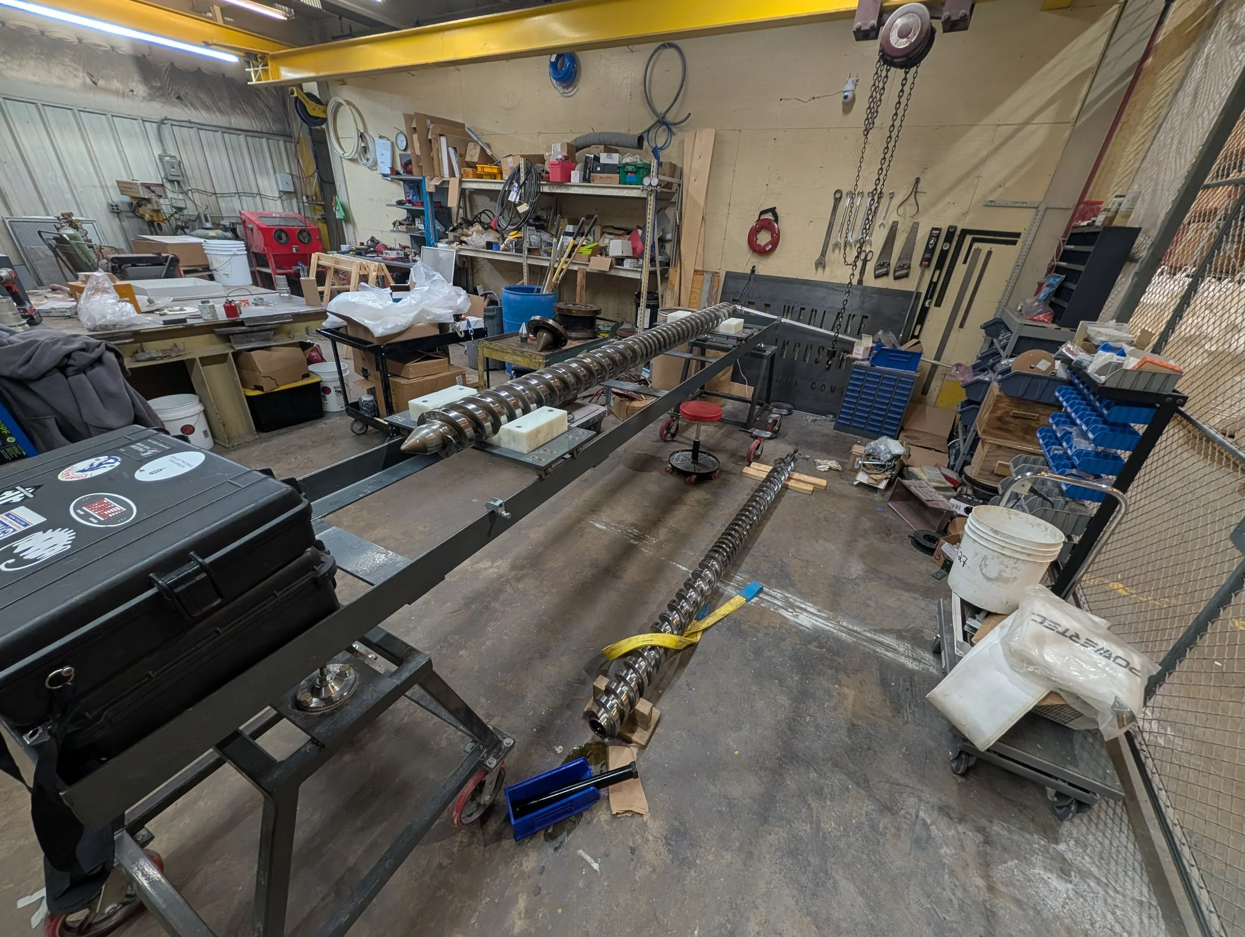
The client operated a plastic compounding facility using a twin-screw extruder — a machine in which two counter-rotating helical screws intermesh to melt, mix, and pressurize polymer feedstock. The screws dated to the 1980s. They were worn and damaged from years of operation, and no engineering drawings or CAD data existed anywhere.
The goal was reproduction by an machine shop. That required more than point cloud data — it required production-ready solid models that reflected the original, undamaged geometry. Worn surfaces had to be interpreted, not just captured.
The bid was structured as a "Do Not Exceed" number — giving the client full budget certainty while ensuring Schimmel Engineering had the time necessary for a high-fidelity interpretative result. If the work ran faster, the invoice would be lower.
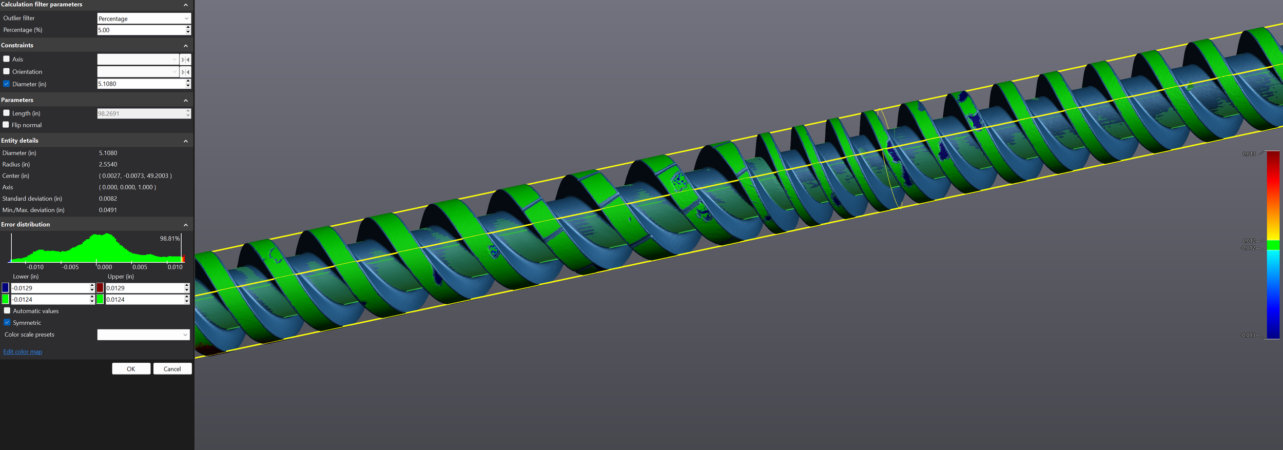
Surface deviation map — best-fit cylinder to screw body. Deviation scale shown left and right. The non-uniform distribution of wear across the screw surface confirms why scan data alone cannot be used for reproduction — the nominal geometry must be sculpted by hand from the scan data — not generated by formula.
Our Approach
On-Site Scan. Interpretative Restoration. Production-Ready Deliverable.
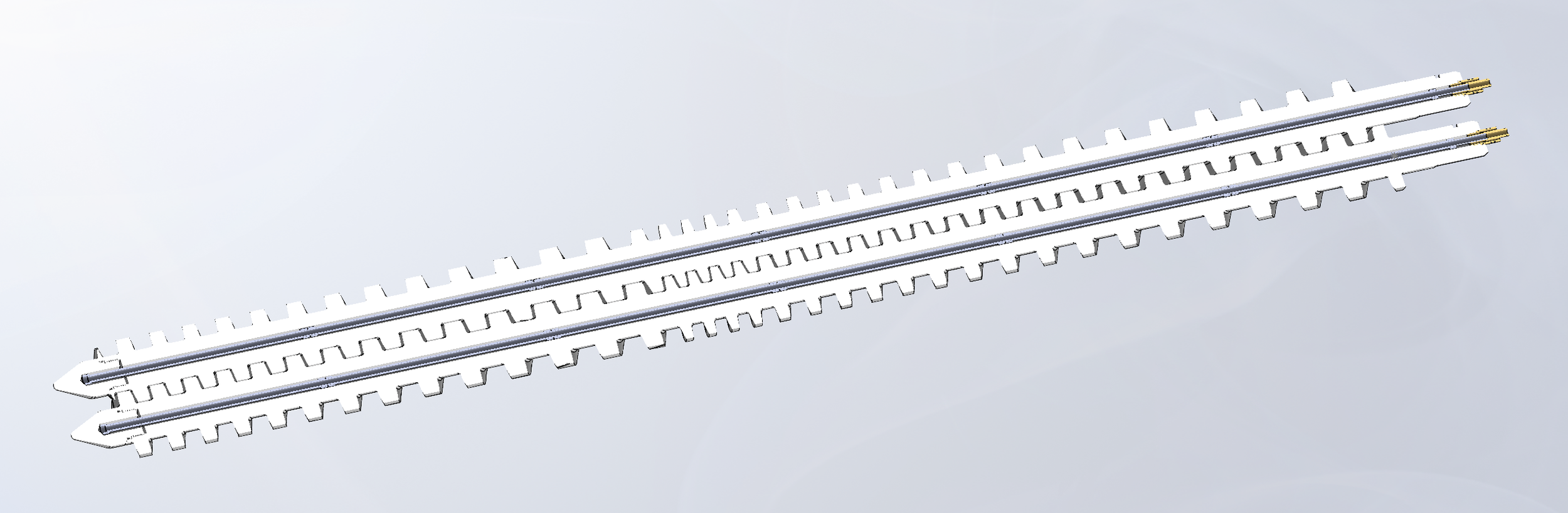
The project began with an on-site visit to the client's facility on April 7, 2026. Both screws were pulled from the extruder drive assembly and laid out in the maintenance bay. Each screw measured approximately 2,438mm × 130mm — nearly 8 feet long. Schimmel Engineering scanned the full geometry of both screws with the Creaform HandyScan Black Elite, capturing all flight surfaces, the spline drive ends, internal cooling passages, brass end fittings, and the complete helical profile.
Because the screws were damaged, the scan data could not be used directly for reproduction. Instead, Schimmel Engineering performed an interpretative restoration. The helical flight geometry was sculpted from the scan data, recovering the original design intent from worn surfaces. The pitch progression, compression ratio, and tooth thickness were analyzed mathematically after the fact to characterize and verify what was sculpted, not to drive the surface creation.
The extruder itself had been discontinued by its manufacturer, who provided no spare parts support — leaving the client with no path to replacement components through normal channels. The analytical plots shown below were generated by exporting B-spline curves from the scan geometry as STEP files, then reading those curves with AI (Claude, by Anthropic) to extract pitch and tooth thickness data along the screw length. AI was also used in conjunction with the scan data to identify the spline drive's module, tooth count, pressure angle, and fit class modifiers. This significantly accelerated the profile identification process and substantially improved accuracy — knowing the exact fit class and profile shift coefficients meant the spline could be modeled to proper standard geometry rather than relying on worn scan surfaces alone.
| Scanner | Creaform HandyScan Black Elite — ±0.025mm NIST-traceable |
| Screw dimensions | ~2,438mm × 130mm OD each (approx. 8 ft × 5 in) |
| Total axial length | ~2,465mm — 18 revolutions |
| Deliverable format | STEP (.stp) and IGES (.igs) |
AI-Assisted Geometric Analysis
Compression Ratio & Tooth Thickness vs. Revolution
The helix geometry was exported as B-spline curves in STEP format directly from the scan software. Those STEP files were then read by AI (Claude, by Anthropic), which extracted the pitch at each revolution, computed compression ratios relative to the reference pitch, and plotted tooth thickness along the full screw length. This approach characterized the original design intent across the full 2,465mm length of each screw — despite the surface damage present throughout.
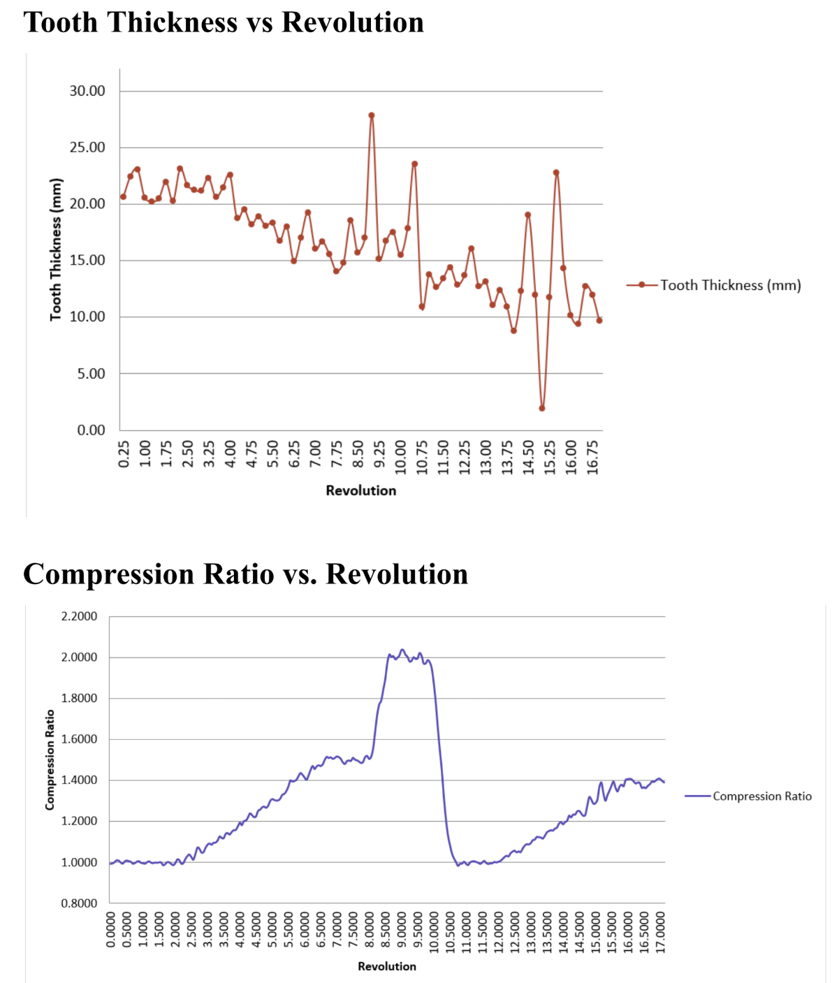
Peak compression ratio: ~2.03:1 at Rev 9–9.5. Feed zone reference pitch: ~180mm/rev. Tooth thickness ramps from ~42mm in the feed zone to a minimum of ~20mm at peak compression, then widens at discharge.
Engineering Detail
Internal Complexity — Cooling, Sealing, and Drive
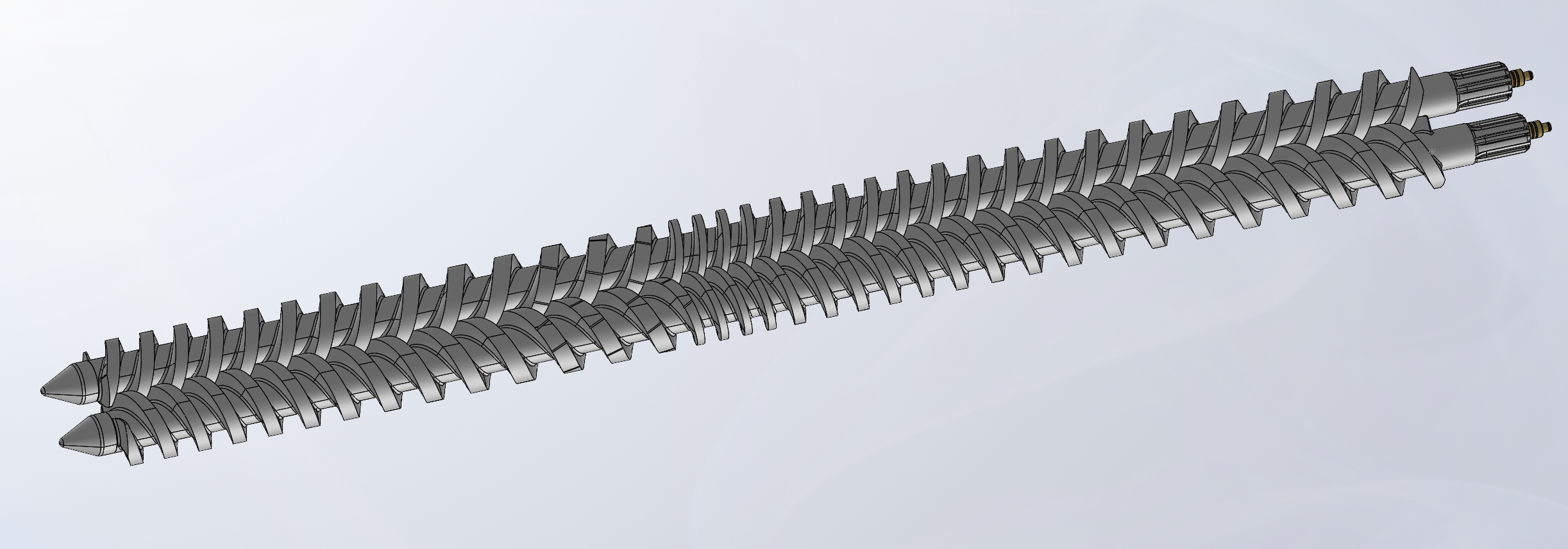
Beyond the external helical geometry, both screws contained significant internal complexity that required full documentation as part of the deliverable package. Each screw is thermally conditioned in operation — heated oil is circulated through internal passages to maintain precise melt temperature. The brass end fittings that supply this heated oil included O-ring grooves and sealing features that were modeled in full detail.
The driven end of each screw terminates in a spline profile that couples to the extruder gearbox. The spline tooth geometry was extracted from the scan data and modeled as a fully dimensioned feature, including tooth profile and engagement length.
All internal and external features — flights, cooling tubes, jacket supports, brass fittings, spline drives, and end geometry — were compiled into a complete exploded-view documentation package with part numbers, enabling the machine shop to understand assembly relationships and identify individual components. A second part inquiry was noted during the project: an adapter endpiece between the screw and extruder barrel, identified as a potential follow-on scope.
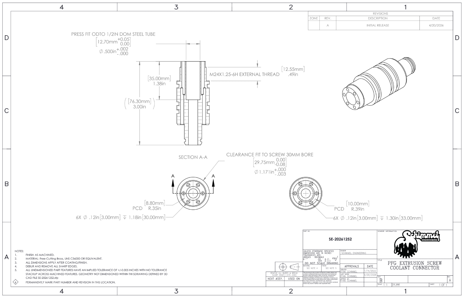
Brass end fitting — O-ring grooves for heated oil supply
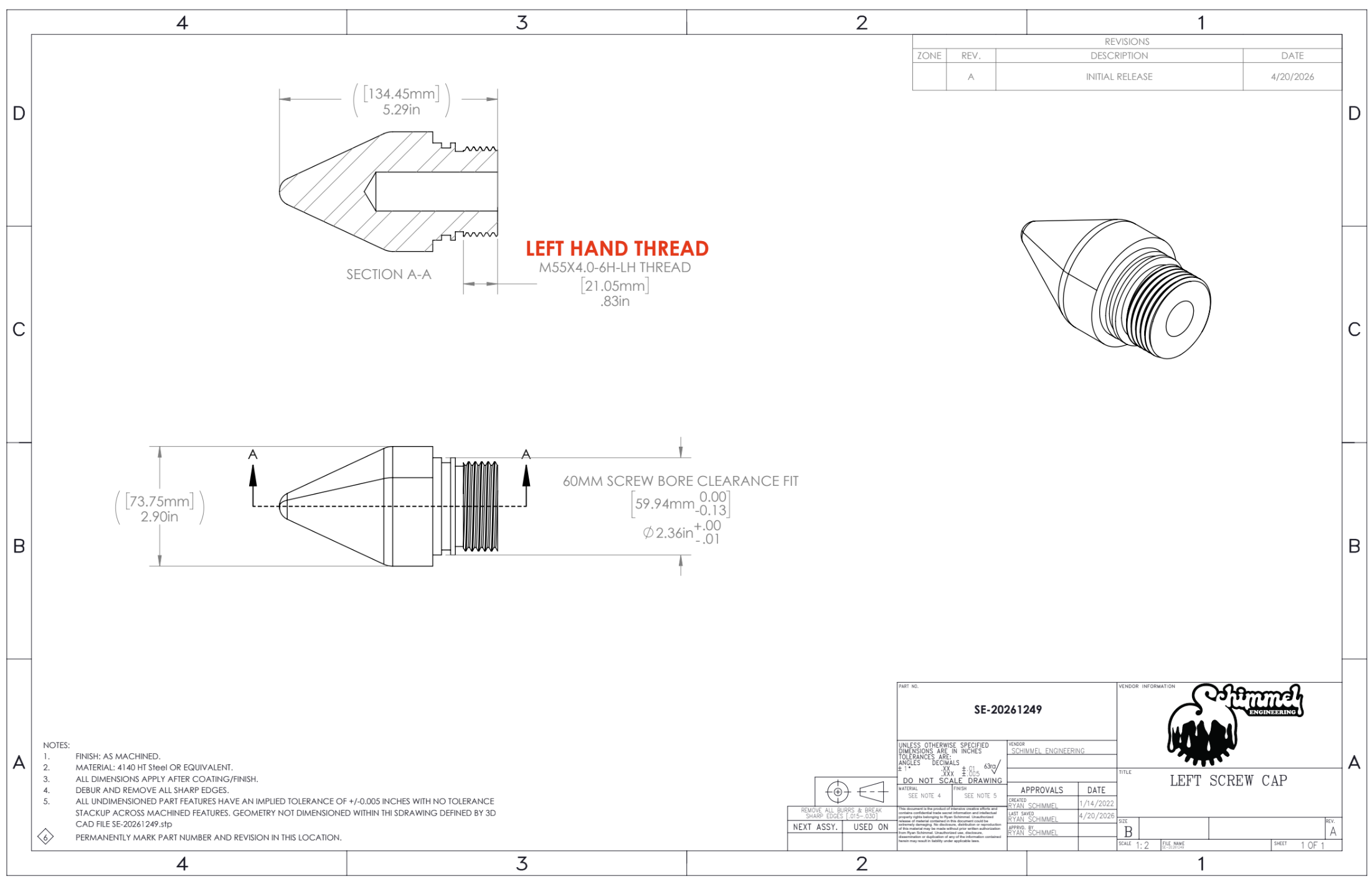
Nose cone — discharge end detail
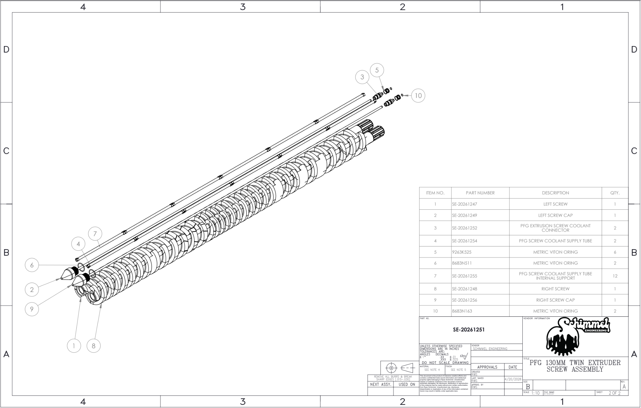
Exploded view with part numbers — full deliverable package
Project Timeline
From Contact Form to Deliverable
Initial Contact
Client submits inquiry via schimmelengineering.com contact form. Two counter-rotating screws for plastic compounding — approximately 2,438mm × 130mm each. Deliverable requested: STEP/IGES solid models for machine shop reproduction. On-site scanning at their Tennessee facility confirmed feasible.
Scope of Work + "Do Not Exceed" Bid
Call held to discuss deliverables and project scope. Scope of Work (SOW.R1) issued as a "Do Not Exceed" bid — giving the client full budget certainty. Project framed as interpretative restoration: not scanning wear and tear, but sculpting the nominal geometry from scan data and verifying it through mathematical analysis.
Green Light — Site Visit Scheduled
Client confirms go-ahead. Site visit scheduled for April 7, 9:00 AM. Screws to be pulled from the extruder drive assembly in advance of the visit.
On-Site Scan Session
Schimmel Engineering arrives at the facility. Both screws laid out in the maintenance bay. Full geometry captured with HandyScan Black Elite — flight surfaces, spline drive ends, brass fittings, internal cooling features, and complete helical profile across ~2,465mm axial length.
Interpretative Restoration + Modeling
Scan data processed in VXElements/VXModel. Pitch extraction and analysis performed across 72 measurement points at 0.25-revolution intervals. Compression ratio and tooth thickness plots generated with AI assistance from STP best-fit line exports. Helical flight geometry sculpted in SolidWorks from scan data. Internal features (cooling tubes, jacket, brass fittings, spline) modeled in full. Exploded-view documentation package with part numbers compiled.
Invoice + Delivery
Invoice submitted. Client requests bill-to amendment; revised invoice issued. Wire payment confirmed Apr 23. Final STEP/IGES models and documentation package transmitted to client for delivery to machine shop.
What This Project Demonstrates
When the Part Is Damaged and the Drawing Never Existed
This project is a textbook case for interpretative reverse engineering. The screws were damaged, old, and geometrically complex — a variable-pitch twin-flight helix with internal cooling passages, thermally conditioned oil supply, and a spline drive end. There were no drawings, no OEM support, and no replacement parts available through any normal channel — the extruder had been discontinued. The machine shop needed production-ready geometry, not a digital record of wear and damage.
The combination of NIST-traceable laser scanning, computational geometric analysis (including AI-assisted pitch extraction from STP exports), and parametric SolidWorks modeling produced a deliverable that met that standard — a complete solid model package with internal features, exploded-view documentation, and the analytical plots that verified the sculpted geometry matched the recovered design intent.
This type of work — recovering original specification from damaged industrial components with no documentation — is one of the highest-value applications of precision 3D scanning. It doesn't require the part to be in good condition. It requires engineering judgment to know the difference between wear and design.
If you have industrial machinery with worn or damaged components and no drawings, Schimmel Engineering can perform on-site scanning at your facility. We service Tennessee and surrounding states, and travel nationally with advance notice. Inquiries welcome for international projects.
Industrial Components With No Drawings?
We perform on-site scanning at your facility and deliver production-ready solid models for manufacturer reproduction. Interpretative restoration available for worn and damaged parts.