NC & StL No. 576 — Locomotive Firebox Distribution Plate Restoration
Case Study — Historic Preservation · Reverse Engineering · Sand Casting
NC&StL No. 576 — Locomotive Firebox Distribution Plate Restoration
Laser scan, reverse engineer, and reproduce two cracked cast iron firebox components for Nashville's historic steam locomotive — with no drawings, no surviving good parts, and a 1% shrinkage requirement for sand casting.
What This Project Demonstrates
When No Drawing Exists and the Part Cannot Be Remade Conventionally
This project had every challenge that makes historic restoration difficult: damaged originals, no documentation, complex geometry, and a casting process with specific requirements. Laser scanning recovered the geometry from the cracked originals. Parametric modeling rebuilt it with correct proportions and casting marks. FDM prototyping validated fit inside the actual locomotive before any foundry work was commissioned. And 3D printed molds made the reproduction economically viable for a volunteer-funded preservation society.
The result is two pairs of production cast iron parts that will go back into a locomotive that last ran decades ago — made from nothing but damaged originals and a scanner.
The Project
A 1940s Locomotive. Cracked Castings. No Drawings.
Nashville, Chattanooga & St. Louis Railway No. 576 — "The Stripe" — is a historic steam locomotive being painstakingly restored by the Nashville Steam Preservation Society. Among the many challenges of restoring a locomotive of this age is the near-total absence of original engineering drawings.
Two cast iron firebox distribution plates — components that direct coal from the stoker into the firebox for combustion — had been damaged. They were welded on incorrectly during a previous repair attempt, creating stress concentrations that caused the castings to crack. The originals were beyond repair, and no replacements or drawings existed anywhere.
The distribution table, with its complex array of holes and internal geometry, would have required a traditional wooden pattern costing an estimated $20,000 or more to produce — the same approach used when the original was cast in the 1940s. 3D printed molds offered a dramatically more economical path to the same result, which is why we chose that route.
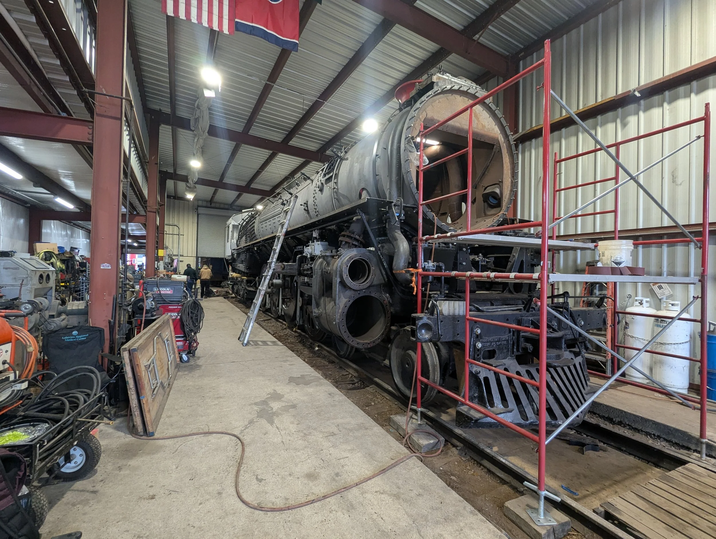
NC&StL No. 576 "The Stripe" — under restoration at Nashville Steam Preservation Society, Nashville, TN
Background
Nashville's Steam Locomotive — A City's Heritage Project
The Nashville, Chattanooga & St. Louis Railway No. 576 is a 4-8-4 Northern-type steam locomotive that once pulled passenger trains across the American South. The Nashville Steam Preservation Society (NSPS) is undertaking the full mechanical restoration of this machine — with the goal of returning it to operational steam service.
The project relies entirely on donations, volunteer labor, and partnerships with local engineering and manufacturing firms. Schimmel Engineering was engaged by Project Foreman Stephen H. to address the firebox distribution plate problem — components critical to the mechanical stoker system that feeds coal into the firebox from below.
The mechanical stoker system moves coal from a tender into the firebox via an auger and distributes it across the grate using steam-powered jets. The distribution plates are the cast iron housings that control that distribution. Without them, the stoker system cannot function — and without the stoker, the locomotive cannot be operated at full steam pressure.
Approach
Scan the Damage. Reconstruct the Intent.
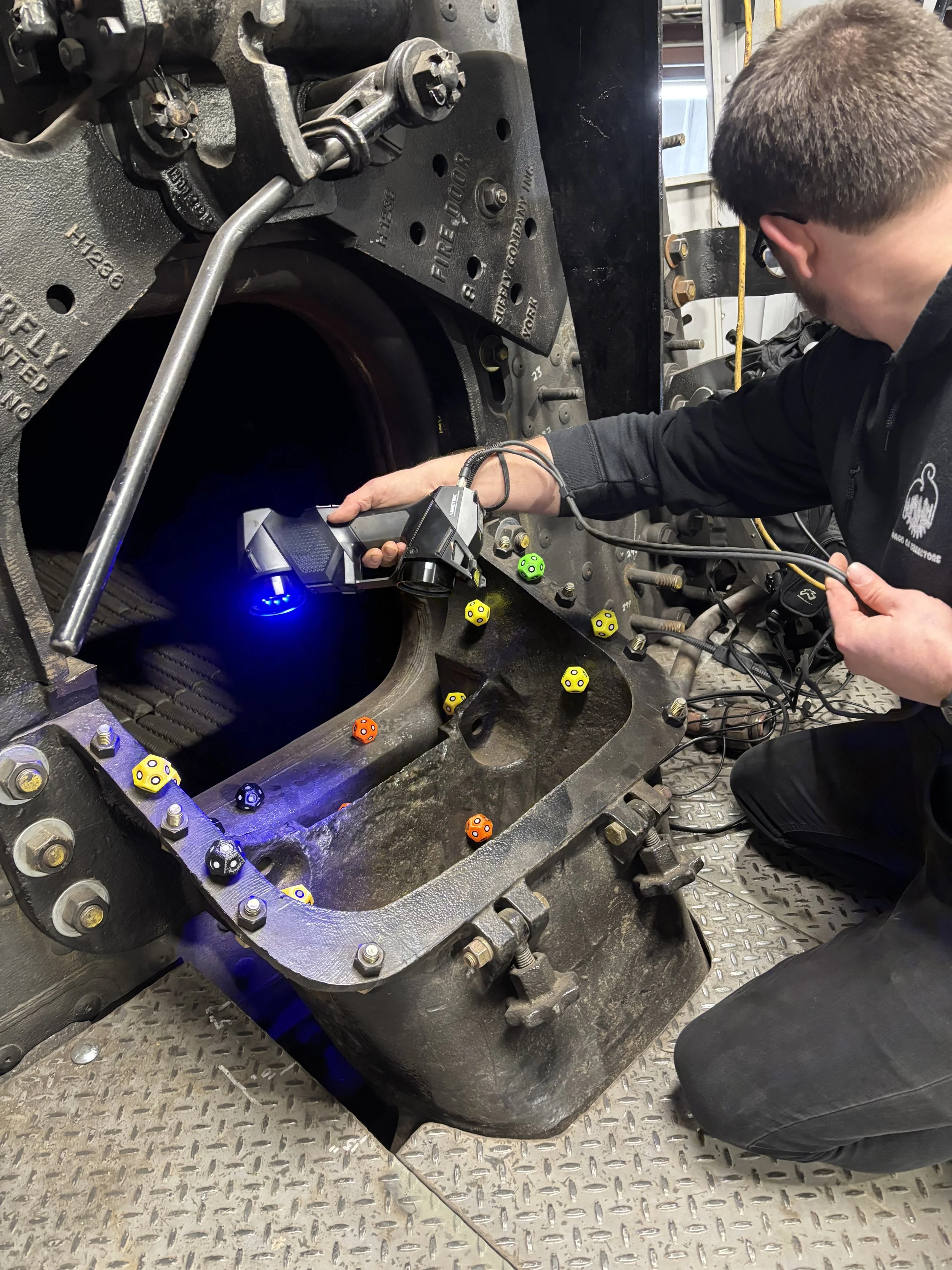
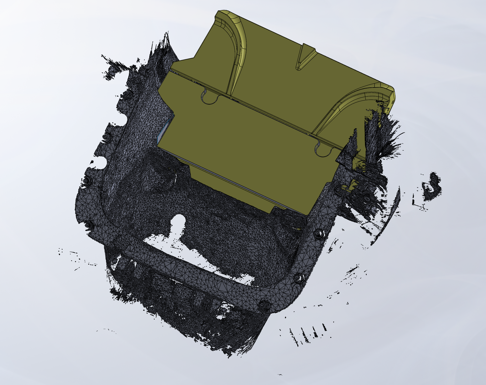
Both damaged distribution plates were scanned with the Creaform HandyScan Black Elite on January 14, 2026. Even in their cracked and welded state, the scan data captured enough of the original geometry to reconstruct the design intent in SolidWorks.
The scan data (purple) was overlaid with the rebuilt NURBS solid model (yellow) to confirm fidelity before any patterns were produced. The hole spacing across the distribution table was found to be asymmetric by 1mm — an original manufacturing characteristic that was preserved in the reproduction. STEP files were supplied to Clarksville Foundry at 100% scale — shrinkage compensation was handled by the foundry in their mold and gating design.
The cast part had no draft angles — the original foundry either used a lost-pattern process or machined the draft after casting. Clarksville Foundry worked directly from the STEP files to determine their own gating and mold layout for the 3D printed mold approach.
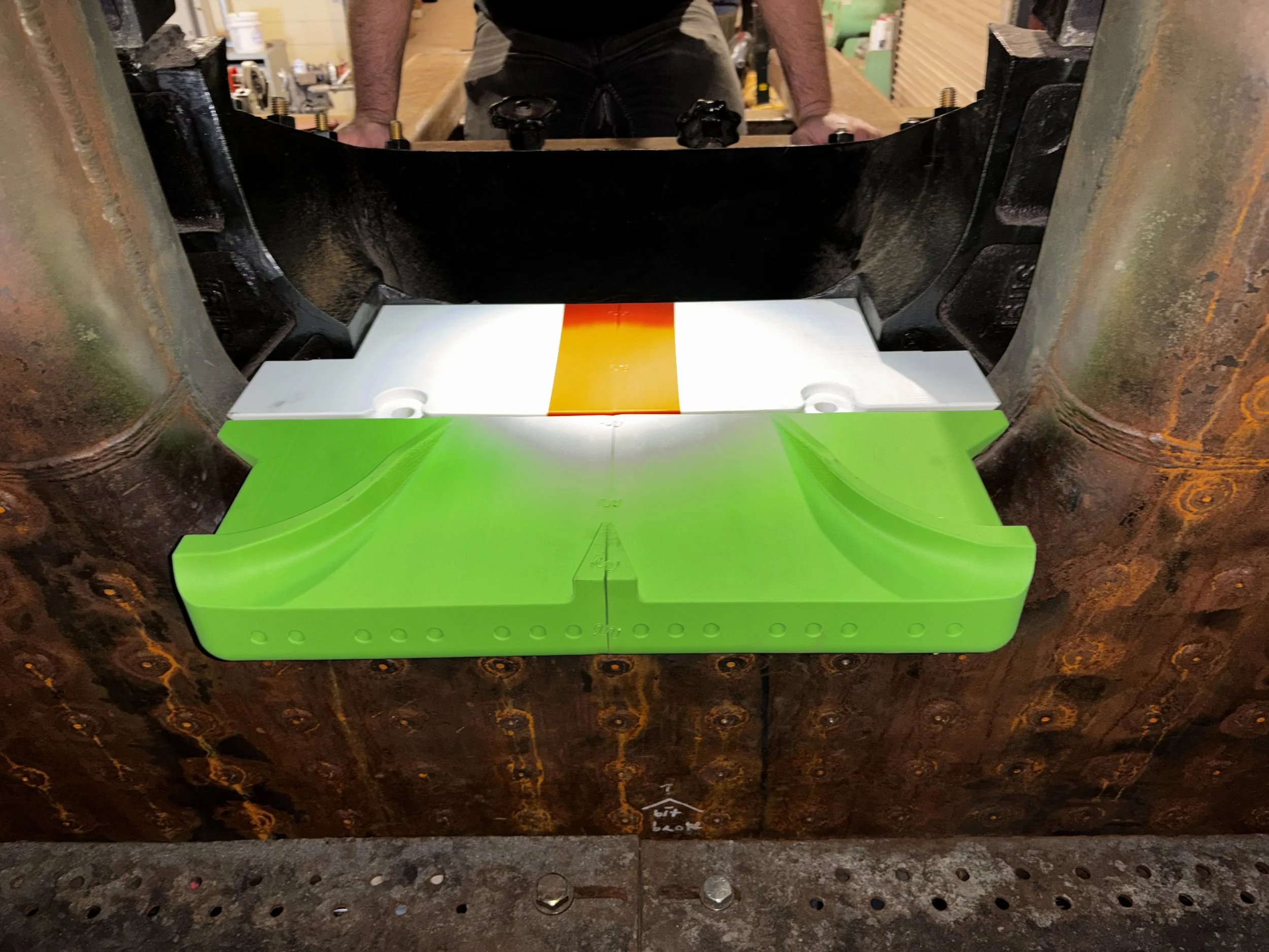
SolidWorks assembly — distribution plates modeled in position inside the firebox. The two plates mate to one another at the coal inlet.
Engineering Detail
3D Printed Molds for Sand Casting — With 1% Shrinkage
Clarksville Foundry in Clarksville, TN was selected as the casting partner. Their engineering team confirmed a 1% shrinkage rate for cast iron in their sand casting process. STEP files were supplied at 100% scale — shrinkage compensation was managed by the foundry in their mold and gating design.
The complex distribution table — with its array of holes, steam passages, and internal geometry — could have been reproduced with a traditional wooden pattern, the same method used when the original was cast in the 1940s. However, a traditional pattern would have cost an estimated $20,000 or more. 3D printed molds produced the same result at a fraction of the cost, making the reproduction economically viable for a volunteer-funded preservation project.
The prints were scanned post-production to verify dimensional accuracy against the CAD model. Some minor revisions were made to boss heights and clearance dimensions after the test fit revealed the boiler front casting had approximately 0.063" clearance each side — requiring tab heights to be increased by 0.25" to allow the final cast parts to be adjusted coplanar after installation. The through holes in the distribution table were produced as-cast with only minor flashing cleanup required — no secondary machining of the hole array was needed.
| Scanner | Creaform HandyScan Black Elite — ±0.025mm NIST-traceable |
| CAD software | SolidWorks 2026 Professional |
| Casting material | Cast iron (grey iron) |
| Casting process | Sand casting with 3D printed molds |
| Foundry | Clarksville Foundry, Clarksville, TN |
| Shrinkage rate | 1% — handled by Clarksville Foundry in mold/gating design. STEP files supplied at 100% scale. |
| Quantity | 2 of each casting (4 total) |
| Prototype method | FDM — ~100 hrs print time — full scale, test-fitted in locomotive |
| Marking | "N.S.P.S." initials + "1Q 2026" cast into surface |
| Through holes | As-cast — minor flashing cleanup only, no secondary machining required |
| Mounting holes | Removed from cast pattern — match-drilled after installation |
| Asymmetry | 1mm hole spacing asymmetry in original preserved in reproduction |
Scan Session
Both damaged distribution plates scanned with HandyScan Black Elite. Schimmel Engineering scans the coal entrance to the firebox.
Foundry Introduction
Stephen introduces Schimmel Engineering to Clarksville Foundry (Dillon Nottingham, Engineering Manager). Shrinkage rate confirmed at 1%. 3D printed mold approach agreed as the path forward.
Meshes Converted to Solid Models
Scan data converted to NURBS/STEP solid models in SolidWorks. Overlay comparison shared with foundry and client. Revision markings (N.S.P.S., 1Q 2026) requested and incorporated.
Three-Way Call — Schimmel Engineering, NSPS, Clarksville Foundry
All parties align on 3D printed mold strategy. Traditional pattern ruled out due to complexity of the distribution table hole array. Full-scale FDM prints approved for test fit.
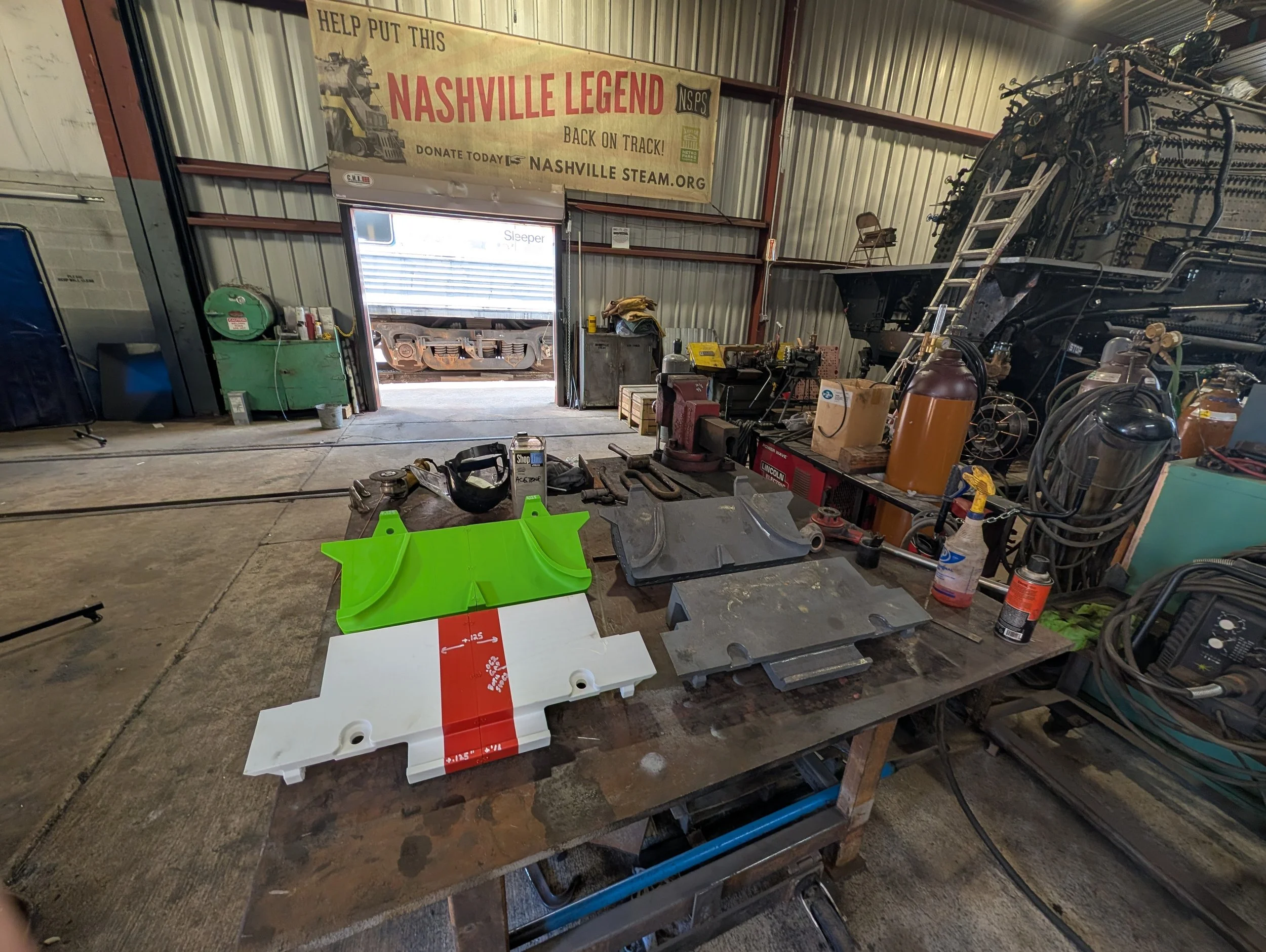
Full-Scale Prototypes Complete
~100 hours of printing. Both distribution plates produced at 100% scale. Inspection report produced and shared. Parts ready for test fit inside the locomotive.
Foundry Quote Received
Clarksville Foundry quotes 2 of each casting using 3D printed molds. Quote approved by NSPS pending dimensional revisions from test fit.
Revised Models Released
Tab heights increased by 0.25" for coplanar adjustment. Clearance confirmed at 0.063" each side. Mounting holes removed — to be match-drilled after installation. Final STEP files (SE-20261236.A) sent to Clarksville Foundry.
Molds Received by Foundry
Stephen confirms molds received by Clarksville Foundry. Foundry schedules pour.
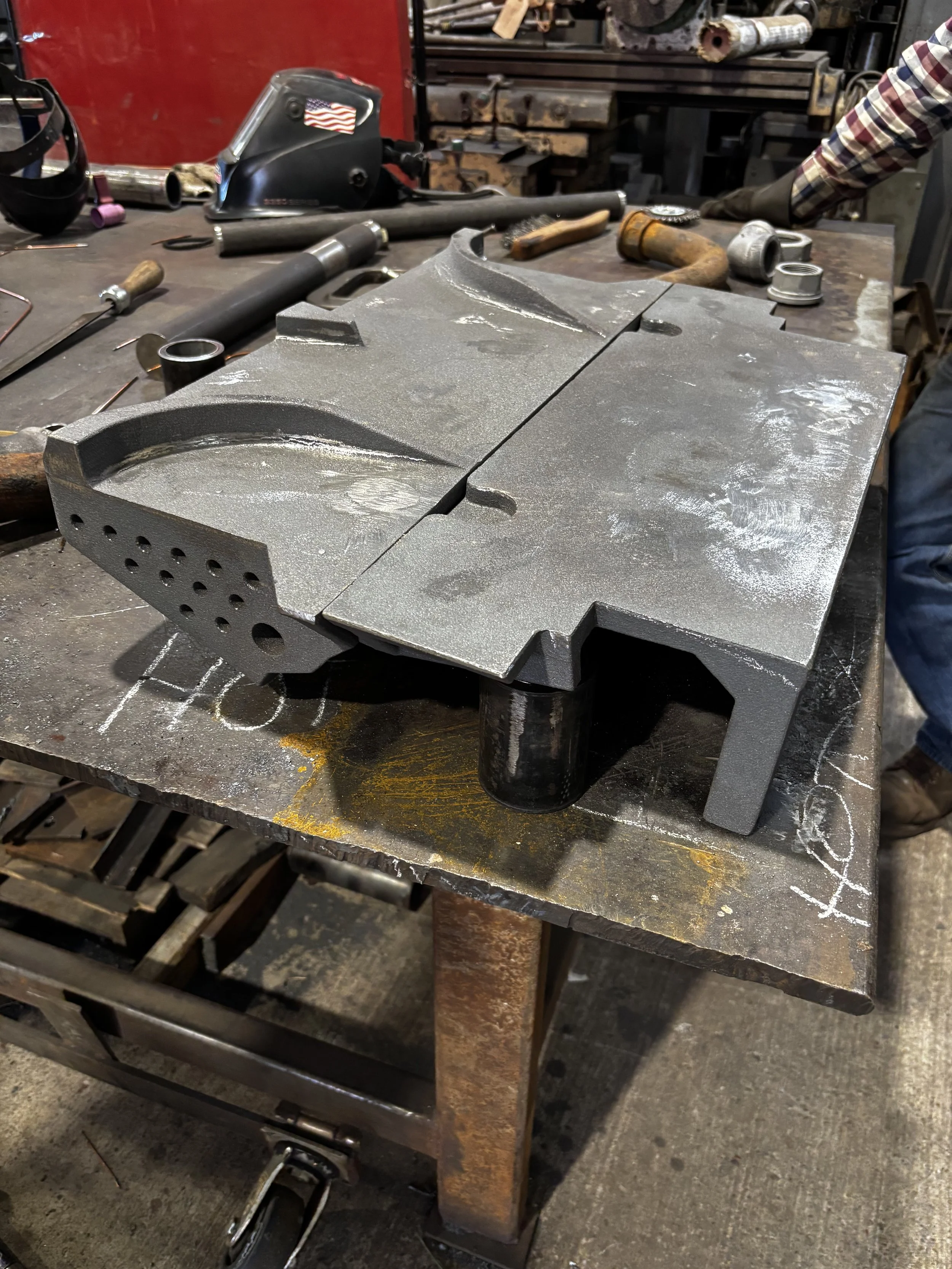
Castings Delivered
"Great news, I received both of the castings yesterday. They look fantastic!!" — Stephen invites Schimmel Engineering to perform a quality check before post-processing.
Good news — I received both of the castings yesterday. They look fantastic!! Feel free to come on by any time to do a quality check, I'm excited to get them fit up!
Stephen H. — Project Foreman, Nashville Steam Preservation Society
Quality Verification
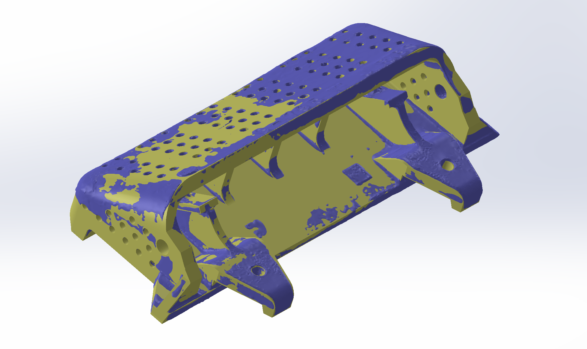
Surface Deviation Analysis — Scan vs. Cast
Following delivery of the castings, a surface deviation analysis was performed comparing the finished cast parts against the nominal CAD model. The color-coded maps below document how faithfully the sand castings reproduce the engineered geometry — accounting for the 1% shrinkage factor applied to the pattern files.
Plot scale: green = ±1mm · maximum range ±3mm. The predominance of green across both parts confirms that the castings are within the expected tolerance band for sand casting. Deviations at edges and complex geometry transitions are consistent with normal sand casting surface behavior and do not affect functional fit.
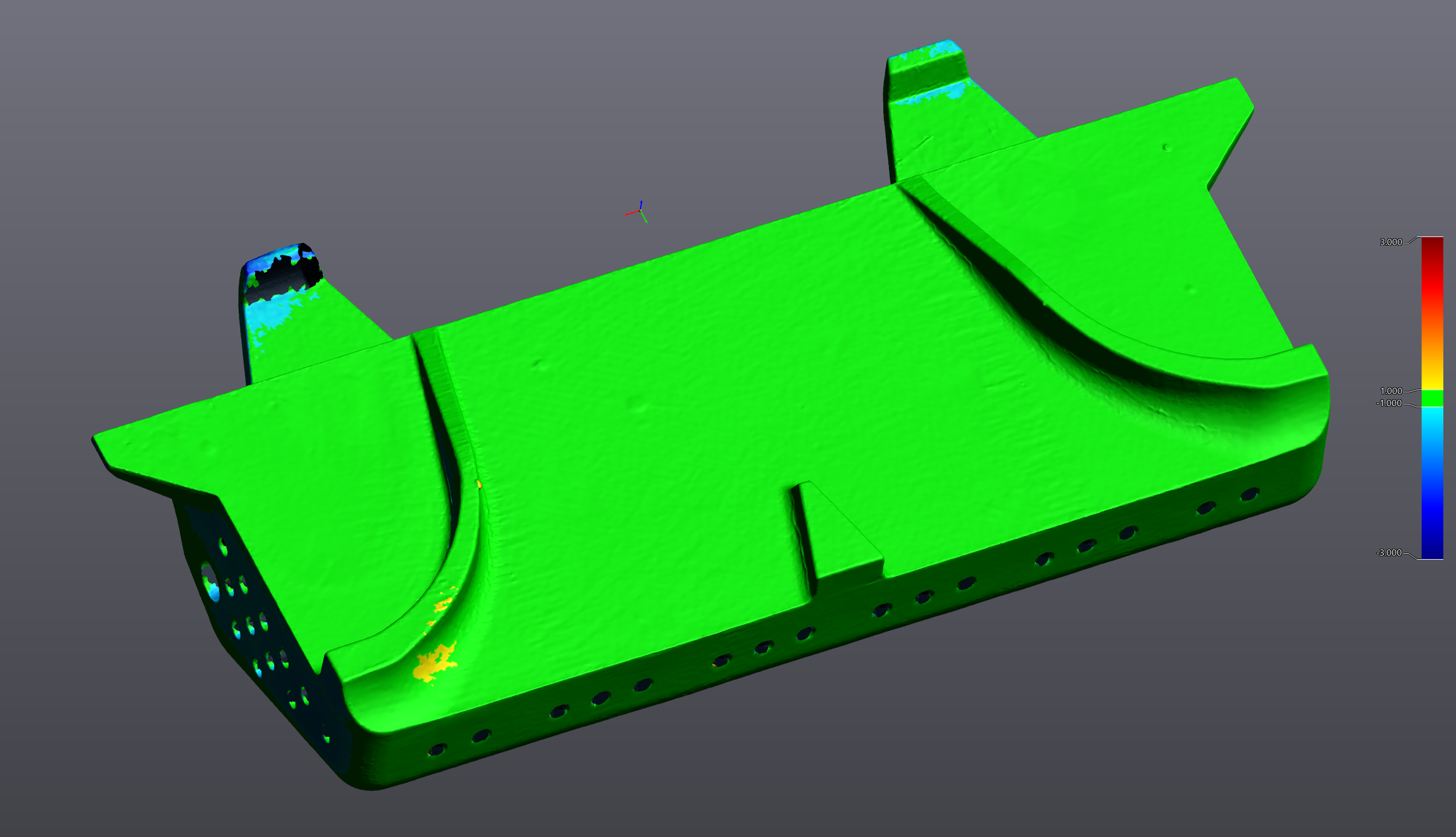
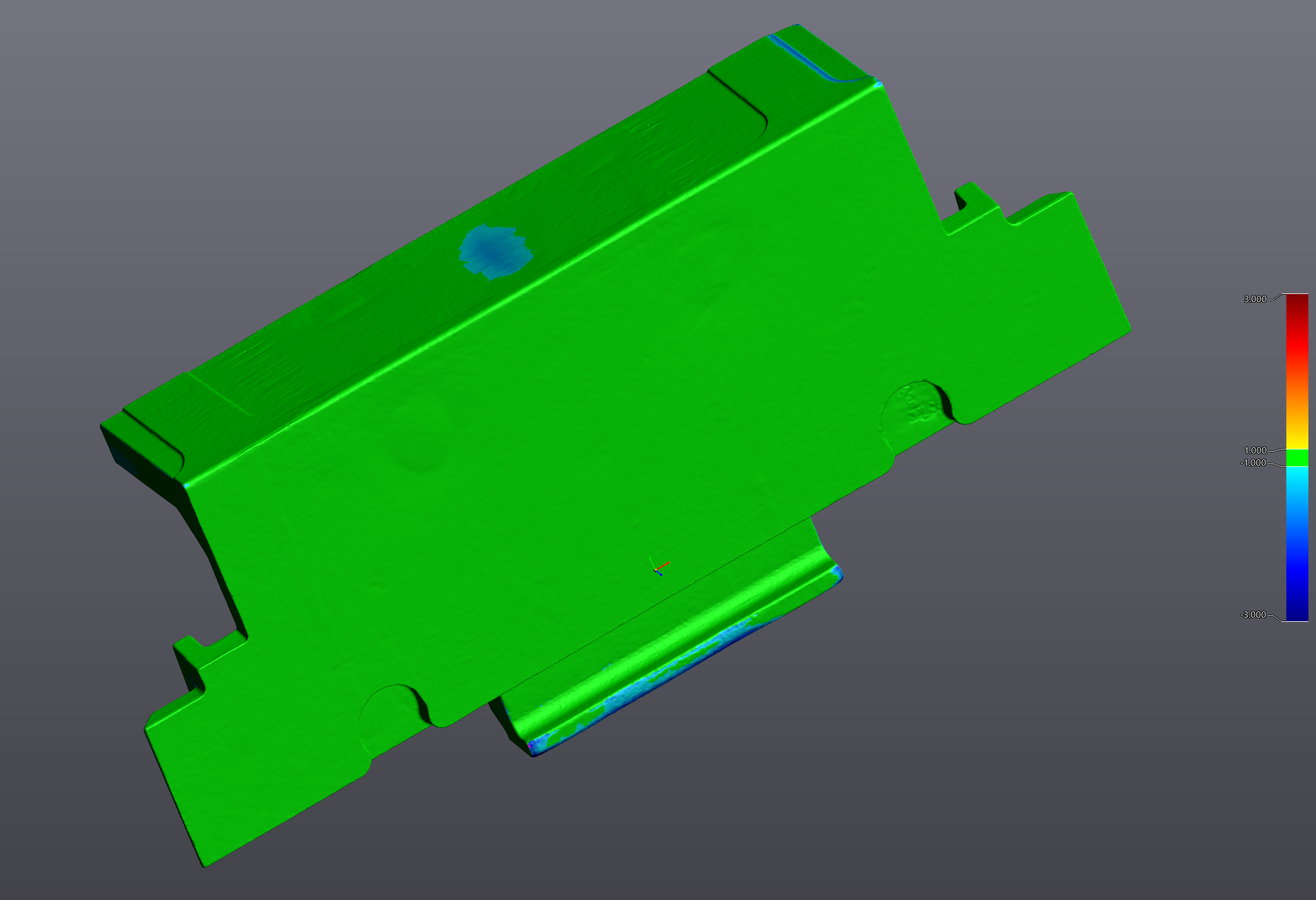
Surface deviation analysis performed in Creaform VXInspect. Cast parts scanned post-delivery and compared against the nominal SolidWorks model. The distribution table (right) shows slightly higher deviation at the hole array edges — expected for sand casting into a complex 3D printed mold. All functional mating surfaces are within ±1mm.
Surface deviation mapping is standard practice for Schimmel Engineering deliverables. Even when a part "looks right," the deviation map provides a documented, objective record that the geometry was faithfully reproduced — critical for components going back into a historic machine where future maintainers need a reliable reference.
Historic Components With No Drawings?
We scan damaged or worn originals and produce production-ready models for casting, machining, or additive manufacturing. On-site scanning or mail-in — nationwide.