
01/ 07
A 3D scanner is just a camera — one that measures distance instead of color.
A regular camera captures how light reflects off a surface and records it as color. A 3D laser scanner does the same thing, but instead of recording color it records distance — precisely how far away each point on that surface is. Do that millions of times per second across an entire object, and you have its exact shape in three dimensions. That's it. Everything else is just what you do with that shape data.
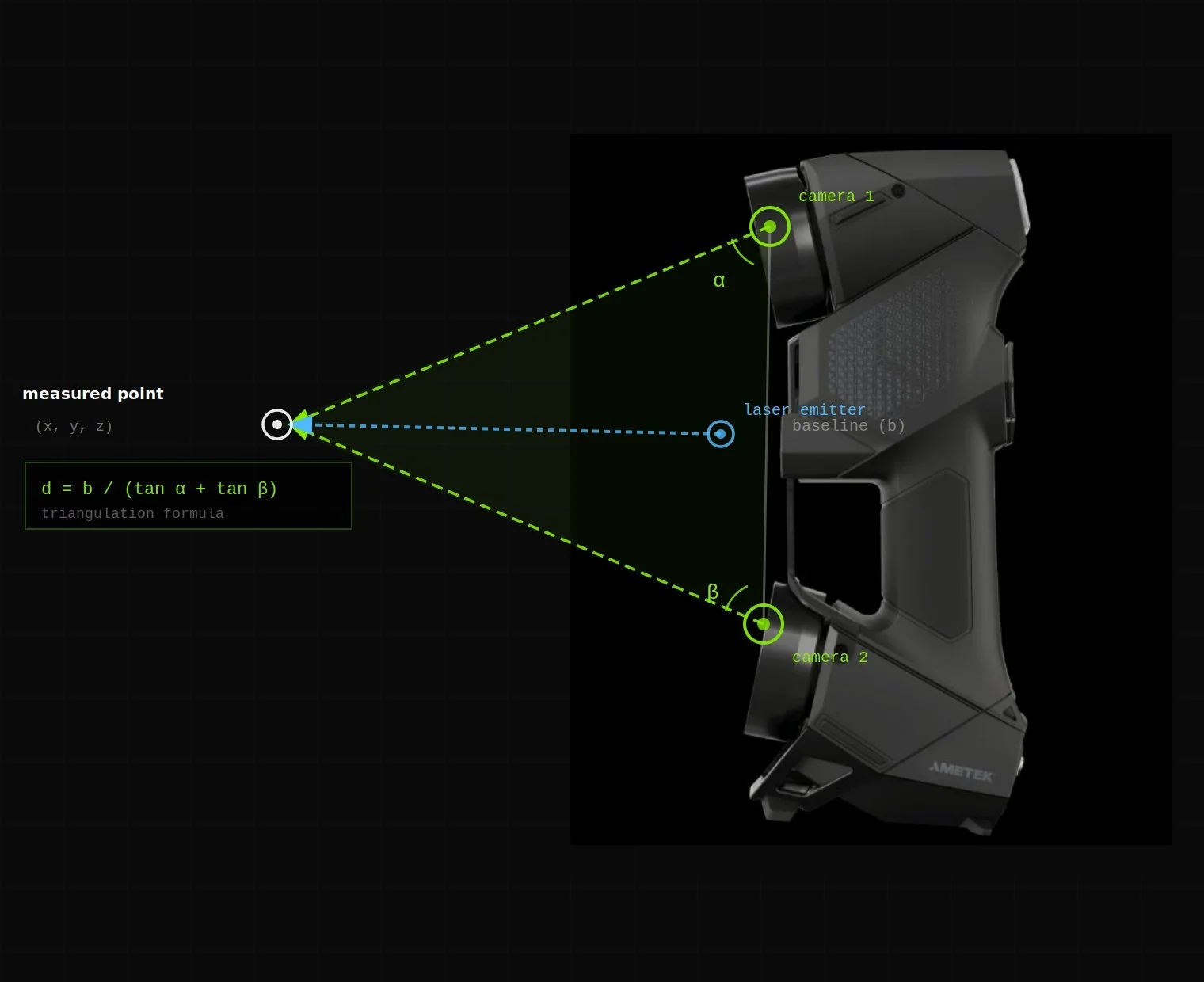
Creaform HandyScan Black Elite — stereo camera triangulation. Two cameras observe the laser reflection from different angles; the intersection calculates the exact 3D position of each point.
The Creaform HandyScan Black Elite uses active stereo vision with structured light triangulation. It projects a pattern of laser crosses onto the surface and uses two calibrated cameras to observe how that pattern deforms. By measuring the angular difference between the projected pattern and its observed deformation, the scanner calculates the precise 3D position of each point via trigonometric triangulation.
This is fundamentally different from time-of-flight measurement (used in LiDAR), which measures the round-trip time of a laser pulse. Triangulation is slower per-pulse but far more accurate at short range — which is why it's the right technology for mechanical parts where you need ±0.025mm, not the ±10mm typical of LiDAR.
The scanner emits 7 laser crosses simultaneously, capturing 1.8 million points per second. It operates at Class 2 laser power — eye safe at normal operating distances. No scanning spray or surface preparation is required for most materials. Highly reflective or transparent surfaces (chrome, glass) may require a light coating of developer spray.
Each scan frame is registered to the previous frame using retroreflective targets (small adhesive dots placed on the part or surrounding surface) and/or feature-based registration for parts with sufficient geometric complexity. The result is a continuous, registered point cloud that covers the entire visible surface of the object.
02/ 07
Not all scanning is the same. The right tool depends on the required accuracy.
Photography-Based
Photogrammetry
Derives 3D geometry from overlapping photographs. You've seen the output — Google Maps Street View and satellite 3D views are built from photogrammetry. Accuracy typically ±1–5mm. Best for large objects, cultural heritage documentation, and situations where a camera is the only available tool.
Pulse-Based / Long Range
LiDAR
Uses pulsed laser light and measures the round-trip travel time to calculate distance. Accuracy typically ±5–10mm. Designed for large-scale environments — building interiors, infrastructure, terrain mapping, autonomous vehicles. Fast over large areas but not accurate enough for mechanical part inspection or reverse engineering.
Triangulation-Based / Metrology-Grade
Handheld Laser Scanning
Uses structured laser light and stereo cameras to measure surface geometry via triangulation. Accuracy ±0.025mm — suitable for GD&T inspection, reverse engineering, and manufacturing. Schimmel Engineering uses the Creaform HandyScan Black Elite, a portable CMM-class scanner, for all scanning work.
Volumetric accuracy describes the worst-case deviation between a measured point and its true position anywhere in the scanner's measurement volume. The HandyScan Black Elite's volumetric accuracy is ±0.025mm — meaning any single measurement point is guaranteed to be within 0.025mm of its true 3D position, regardless of where the scanner is positioned relative to the part.
This is distinct from resolution (the minimum spacing between captured points) and repeatability (how consistently the scanner produces the same result across repeated scans). All three matter for different applications:
- Accuracy matters for first article inspection and GD&T verification against a nominal CAD model
- Resolution matters for capturing fine surface detail — threads, radii, sharp edges
- Repeatability matters for production inspection where the same part is measured repeatedly
For comparison: a standard caliper has accuracy of ±0.02mm but measures only one point at a time. The HandyScan captures 1.8 million points per second at ±0.025mm — providing complete surface coverage rather than spot measurements.
The scanner is NIST-traceable, meaning its calibration is traceable to national measurement standards maintained by the National Institute of Standards and Technology. This is a requirement for aerospace, defense, and regulated manufacturing inspection work.
04/ 07
The points are connected into a mesh — a complete digital shell of the object.
A point cloud is just dots. A mesh connects those dots into a continuous network of triangles — covering the object from end to end with no gaps. The result is a watertight 3D model you can rotate, measure, and view from any angle. A mesh file is the first usable deliverable from a scan, and for many applications — 3D printing, visual reference, mold making — it's all you need.
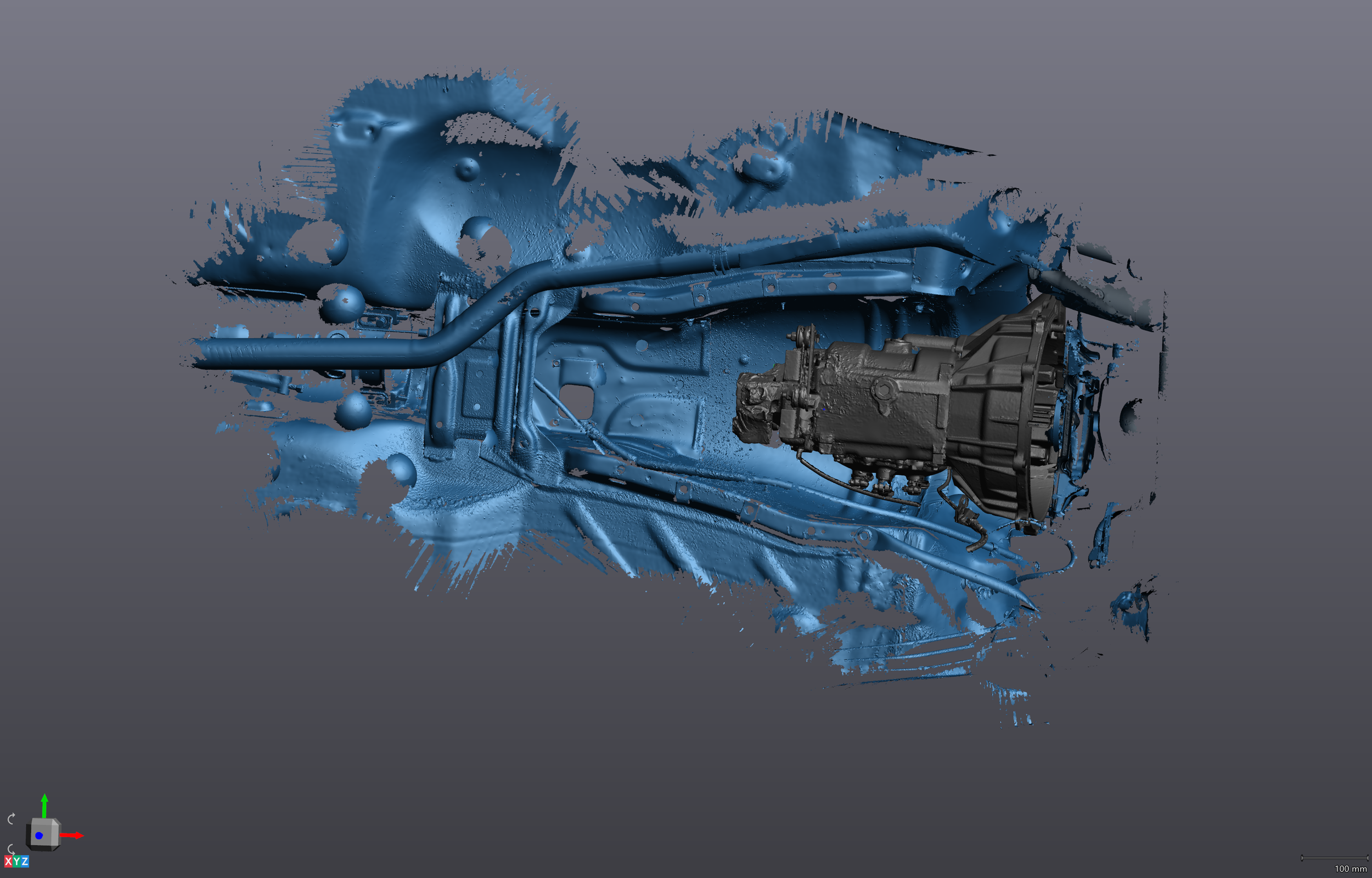
Creaform VXModel — the same scan data, now processed into a triangulated mesh
A polygon mesh represents geometry as a collection of vertices, edges, and faces — typically triangles in scan-derived meshes. The quality of a mesh is described by several parameters:
- Triangle count: Higher triangle counts preserve fine detail but produce larger files. A typical mechanical part mesh ranges from 500,000 to 5 million triangles. Schimmel Engineering delivers both full-resolution and 80%-decimated meshes as standard — the decimated version is easier to handle in downstream software.
- Watertight (manifold) mesh: A mesh with no holes, non-manifold edges, or self-intersections. Required for 3D printing, FEA analysis, and CAD import. Most raw scan meshes require post-processing to become watertight — filling scan shadows, smoothing noise, and repairing artifacts.
- Raw mesh: The unprocessed triangulation of the point cloud. Useful for inspection workflows where you want to preserve every measured point, including surface texture and noise.
Mesh files are delivered in STL (stereolithography — universal, no color) and OBJ (Wavefront — supports color/texture maps) formats. Both are compatible with all major CAD, slicing, and inspection software.
Importantly: a mesh is not parametric. It describes shape as a triangulated shell — not as engineering features. You cannot directly dimension a mesh, apply tolerances, or modify features the way you can with a parametric CAD model. The mesh is the starting point for parametric reconstruction, not the end point for manufacturing.
05/ 07
From the mesh, an engineer rebuilds the part — not traces it — with manufacturing intent.
The mesh tells you the shape. A parametric CAD model tells you the intent. An engineer looks at the mesh, understands what each feature was supposed to be — a machined bore, a filleted edge, a drafted wall — and rebuilds it using the tools a machinist or fabricator actually uses: extrudes, revolves, holes, fillets, and tolerances. The result isn't a copy of the scan. It's an engineered model that a machinist can read and reproduce correctly.
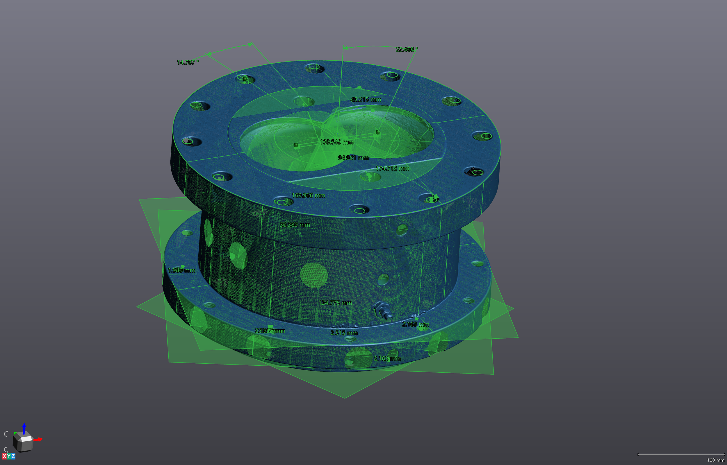
VXModel — best-fit geometric primitives (cones, cylinders, planes) fitted to raw scan data. These become the features in the parametric model.
Parametric modeling from scan data follows a structured workflow that Schimmel Engineering performs in SolidWorks 2026 Professional with reference to the processed mesh:
- Datum extraction: Identify primary, secondary, and tertiary datum planes from the scan geometry. These become the coordinate system for the model and the reference for all GD&T callouts.
- Feature identification: Interpret what each region of the mesh represents as a machining or fabrication operation. A cylindrical region is a turned bore or boss — not just a curved surface.
- Nominal geometry reconstruction: Fit idealized geometry to the scan data. A bore that measures 24.97mm after years of wear is modeled as 25.00mm — the design intent — unless the application requires an as-built nominal.
- Tolerance application: Assign GD&T callouts based on functional requirements, mating interface criticality, and manufacturing process capabilities. This is engineering judgment that the scan itself cannot provide.
- Validation: Import the completed model back into inspection software and compare against the original mesh. Deviation mapping confirms the model accurately represents the scanned part within specified tolerance bands.
The output is a fully history-based SolidWorks part file (.SLDPRT) with a complete feature tree — every extrude, revolve, and fillet is editable. Neutral formats (STEP AP214, IGES) are also exported for use in other CAD platforms.
A CAD model tells a machinist the shape. A manufacturing drawing tells them the requirements — which dimensions are critical, what tolerances apply, what surface finish is required, and what material to use. Most domestic CNC shops can work from a STEP file alone for simple parts. For anything with:
- Critical fit interfaces (shaft/bore, press fits, clearance fits)
- GD&T requirements (flatness, perpendicularity, true position)
- Surface finish specifications (Ra values, post-processing requirements)
- Overseas manufacturing (drawings prevent ambiguity across language barriers)
- Legal or regulatory documentation requirements
...a fully dimensioned manufacturing drawing is required. Schimmel Engineering produces drawing packages in SolidWorks Drawing format exported to PDF and DXF/DWG, formatted for both domestic and international vendors. Drawing packages typically add $500–$1,000 over the base CAD model fee depending on part complexity and number of sheets.
06/ 07
The full journey: physical part to vendor-ready file.
Every scanning project follows the same five-stage data pipeline — from capture to deliverable. The time and cost at each stage depends on what you need at the end.
01
Capture
Laser scanner records millions of coordinate points across the part surface. 10–45 minutes typical.
→02
Point Cloud
Raw coordinate data is registered, cleaned, and aligned into a unified 3D dataset.
→03
Mesh
Points are triangulated into a watertight mesh. STL & OBJ deliverable. From $195.
→04
Parametric CAD
Engineer rebuilds the part in SolidWorks with design intent, features, and tolerances. STEP, IGES, SLDPRT. From $250.
→05
Drawings
GD&T manufacturing drawing package for domestic or overseas vendors. PDF & DXF. Add $500–$1,000.
07/ 07
The deliverable is a file your machinist, printer, or vendor can use today.
Different recipients need different formats. A 3D printing service needs an STL. A machine shop needs a STEP file or a drawing. An engineer working in a different CAD platform needs IGES. The right format isn't a preference — it's determined by what the downstream software or process requires.
| Format | Type | Use Case | Who Needs It |
|---|---|---|---|
| STL | Mesh | 3D printing (FDM, SLS, MJF, DMLS), visual reference, mold design starting point | 3D printing services, mold makers, product designers |
| OBJ | Mesh | Same as STL, with optional color/texture map support | Visualization, heritage documentation, game/VR asset pipelines |
| STEP (AP214) | Neutral CAD | CNC machining, casting, fabrication — universal CAD exchange format | Machine shops, fabricators, any engineer not using SolidWorks |
| IGES | Neutral CAD | Older neutral format, widely supported — use STEP when possible | Legacy CAD systems, older vendor workflows |
| SLDPRT | Native SolidWorks | Fully parametric, history-based model with editable feature tree | Engineers using SolidWorks who need to modify or extend the model |
| PDF / DXF | Drawing | Manufacturing drawings with GD&T, tolerances, material callouts | Any machinist or fabricator, especially for overseas manufacturing |
STEP AP203 transfers solid geometry and topology — the shape and how surfaces connect. It does not transfer color, material, or assembly structure metadata. Supported by all major CAD platforms since the mid-1990s.
STEP AP214 is a superset of AP203 that adds color, layer information, and limited metadata. Use AP214 when transferring assemblies with visual organization or when the recipient's CAD platform supports it. This is the format Schimmel Engineering exports by default.
IGES (Initial Graphics Exchange Specification) predates STEP and has known limitations: it transfers surfaces rather than solids, can produce open shells that need repair in the receiving software, and has less consistent implementation across CAD platforms. Use only when the receiving system doesn't support STEP.
For overseas manufacturing vendors — particularly in China and Southeast Asia — STEP + PDF drawing is the most reliable combination. STEP eliminates unit confusion (millimeters are encoded in the file), and the PDF drawing provides the tolerance and finish information that a STEP file alone cannot convey.
Ready to scan something?
Now that you know how it works — here's what we can do with it. Mail-in scanning starts at $195. On-site visits start at $390. Consultations are always free.